Saturday, 22 June 2013

BRAKE LIGHT SWITCH

My scooter never had a stop light switch fitted as I guess this was fitted to the later models in response to legislation.  I had a look through various web sites and Blogs in the hope of finding how best to fit a switch.  The best I found was at billy192.blogspot. There is a picture of the switch mounted to the frame.  I particularly like the switch that was shown as it had a metal body. 


 I looked everywhere (if you Google "motorbike brake switch" using images you pretty soon get fed up with the options available) and couldn't find a suitable one with a metal case.  In the end I had to settle for a switch with a plastic body but with two lock nuts so that I could adjust the position of the switch in its mounting.

The switch can be bought for under a fiver and comes complete with the coupling spring 


Having found a switch the next problem was how to mount it.  Billy192 had gone for a bracket secured to the center tube using a couple of pipe clips.  I fancied a different approach.  I even considered welding a bracket to the frame but discounted this on the grounds it would be permanently altering the frame.  


 I decided that I could design a bracket that would only need a single hole to be drilled in the existing rear brake cable bracket.  This proved much more difficult than I had anticipated.  Having no right angle drill (something for next Christmas) I couldn't get a conventional drill into position.  In the end I managed to use a chuck and turn it by hand.  Starting with a 2.0mm drill I progressively opened the hole to the 5.0mm I finally needed.  It's a very slow process!


Trying to visualise a bracket can be difficult.  I have found in the past that the process can be speeded up by using paper or card.  This allows me to change things quickly before I attempt using metal.

In this case I used a scrap piece of paper and cut and folded it until I was confident that it would work.  It showed me where the critical dimensions were and allowed me to think how I was going to make it.


 This is my final bracket.  Its a bit different from the paper version but then that is the point of the paper prototype.  It allows you to see where things need adjustment.

The 5.0mm hole allows the the bracket to be "pulled" into the bracket on the frame.  The top flange prevents the bracket from twisting.  It is difficult to obtain a tight fit with two bends especially since the top bend is not parallel to the bottom bend.  To overcome this I made the bracket in two parts and welded them together.  In this way I could I could adjust the fit before welding.


The next task was to find a way of connecting the switch to the foot brake.  My switch required a pulling action for the contacts to be made.  There are no obvious attachment points and I didn't want to modify the actual pedal lever itself.  (I guess I could have found a different switch which would have been operated by the pedal lever pressing against it.  The switch would then have had to be mounted in front of the lever in a more exposed position.)
The actual movement of the brake cable is about 3.0mm.


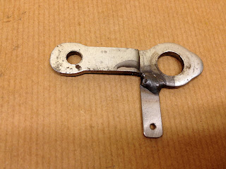
My solution was to modify the inboard of the two cable clamping plates.  Welding a strip of steel to the clamp plate provided a point to attach the brake switch plunger.


This how the components are configured


The final installation


Using a buzzer across the switch leads I adjusted the two securing nuts until the switch made contact after approximately 1.0mm of cable movement.  Once the switch contacts have made further travel of the cable is taken up by the spring section. 


In Conclusion?  I think it will work as a stop light switch.  It's reasonably protected by the brake lever assembly both mechanically and environmentally.  How could I have improved the design?  Looking at "billy192's" configuration he has mounted his switch above the brake cable bracket so that it is less vulnerable.  I think this is a better position but at the time I did not fit the legshield to check clearance, perhaps I should.

Saturday, 15 June 2013

THE BATTERY TRAY

For no particular reason I fancied moving on to the battery tray next.  It was obvious that I was going to need new battery straps as these had been cut off at somepoint

Before I can decide how best to replace the battery retaining straps I need to know what battery I am going to fit.  I have two alternatives, fit a genuine Lambretta battery or a modern alternative.

I contacted Lee at Scootopia, (was Casa Lambretta) (they really are so helpful) and he went away and measured a real Lambretta battery for me, W 125 - D 35 - H 127I trawled the internet and found a number of reasonable alternatives despite them being larger in most cases.  I liked the YUASA battery at Allstyles-scooters for £30 ish with a size of W 122 - D 46 - H 125 and a capacity of 7Ah.  I could now make some decisions.

Non standard tray with straps cut off
I was suspicious of the plate at the back as it was made of much thinner material than the rest of the tray.  The tray was a lot wider than the Lambretta size and when I removed the rubber mat in the bottom of the tray I could see why.

The tray had been modified by bending the back flange down and attaching a thin plate.  I guess to accommodate a non standard battery.  I can see the sense of this as Lambretta battery is very expensive at around £70.  


I need to decide what standard I'm trying to achieve.  If Concourse I will have to have the correct battery, if not I can use a cheaper alternative.  I think the non concourse route is the one for me.   

My original concern to have any welding completed before I filled the tank with fuel included fitting new battery straps.  This problem was solved when I discovered that the battery tray is removable, I had thought It was welded as part of the frame. It is in fact attached to the frame by two screws.  With the paint removed I was able to drill out the rusted screws and release the tray.

I have subsequently been able to buy from Terry, a contact, an original battery tray so I now have the opportunity to revert to the correct battery and tray configuration if I change my mind at a later date.


The top tray is from my scooter.  The original battery strap can be seen in the base of the tray where it has been cut off what was the side.  Even the extended back plate has evidence of a strap that has been removed. 

The lower tray is an original  that I bought  just in case I ever wanted to fit an original battery.


I intend to rebuild the extended tray to make it like an over sized original.  This has the advantage that it gives me a wider selection of cheaper batteries.  I eventually ordered the battery from Allstyles Scooters (B396-6) at £29.95 (I was subsequently told that a similar battery should be available for around £15, do I feel gutted?).  With the battery available I was ready to work on the old tray and the battery restraining strap.

I first I removed the tall back plate and the old ends of the retaining straps. The backplate was replaced with a strip of material the same width and thickness as the other three sides to complete the tray.  With this welded into position I could start work on the retaining straps.

I had previously looked at as many pictures of the original strap configuration as I could find.  There seemed to be a number of options.  I liked the idea of replicating them as far as possible but once I found that there  appeared to be no definitive solution I decided to develop my own.  I liked the idea of being able to fold part of the outside strap down to allow the battery to be more easily removed.  (a bit daft actually because I'm unlikely to ever remove the battery once the scooter is running but it was a good idea at the time).


I hate using tin shears to cut thin sheet.  It always results in the bit you want being twisted like a piece of apple peel.  Despite trying to flatten the material it is never quite right.  So without access to a guillotine I resort to my other favorite technique - the hacksaw.

This may be a bit slow but with the sheet securely clamped and using a fine toothed hacksaw blade at least you end up with a nice flat strip of material.  


The finished battery tray and strap.  the folded down section makes for easy fitting of the battery.  The original straps are spot welded to the tray.  I had visions that if I ever wanted to transfer my straps to the other tray welding was not an option.  I therefore elected to tap M3 threads into the tray sides and secure each strap with two M3 roundhead screws.


The tightening of the strap uses a pair of trunnions and tray screw purchased from Allstyles Scooters.  The trunnion on the right has a clearance hole whilst the one on the left is tapped M5.  The spacer between the head of the screw and the trunnion is because the head rubs on the strap.  I'm not too sure I like that but I can always turn down the head of the screw if it continues to offend me.


The final assembly fit well inside the scooter frame and does not touch anything.   I have to say that the actual "clamping" of the battery is adequate but not exceptional.  The battery will not fall out and should not move too much but I may have to adjust the trunnion position so that I can further tighten the strap.  If I apply this to the outer trunnion I may be able to dispense with the spacer which would be nice.


 i think I need to start thinking about the harness soon.  I seem to have a lot of wires in place where I wasn't expecting them.  I also need to find a way of providing a stop light switch.  Still more fun to come.