Wednesday, 3 April 2013

SEAT SPRINGS


I had trawled the internet to search for replacement seat springs for an LD 150 Mk 2.  There appeared to be new ones available for dual seats as fitted on the later models but nothing for my front and rear seats.

The original springs are 8.0mm diameter with a wire thickness of 1.6mm, 13 for the front seat and 11 for the pillion seat 

Whilst searching I came across a really good blog, "Lambretta LD Restoration" which had a very useful entry on seat restoration ( http://billy192.blogspot.co.uk/2011/11/stage-3-with-lambretta.html ).  He also had the problem of sourcing springs and had read of someone else making his own using a flexible drain cleaning spring from B&Q.


B&Q 6ft Spring Spiral Drain Cleaner  
Length 6ft  (1.8m)
cost about £7 
Spring diameter 5.5mm
wire thickness 1.2mm
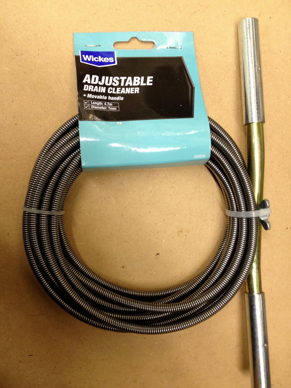
Having looked at the B&Q spring I felt that it was too weak.  I discovered that WICKES have both a similar version and a heavier one.  This time I took my vernier calipers with me and found  the size to be closer to the original seat springs.

WICKES Adjustable Drain Cleaner
part No  W500594W
Length 4.7m
Cost approximately £15
Spring diameter 7.4mm  
wire thickness 1.4mm.

Note:-  this provided sufficient for all 26 springs and some left over.


With two options for the replacement springs I couldn't resist the temptation to check the spring rates, I didn't have much choice but I wanted to know where they were compared to the originals.  My test was simple, I fixed one end of the spring in a vice and attached the other end to a spring balance.  I stretched the spring 0.5 inches and noted the load on the balance.  Not very accurate but the results were as follows:-

                          ORIGINAL       11 lbs

                          WICKES          21lbs

                          B&Q                 8lbs

Despite the higher reading the WICKES spring felt best so I went ahead and started making the springs for the pillion seat. 


 The spring is supplied with both ends terminated ready for drain clearing.   Firstly cut off one of these ends in readiness to form the hook end for attaching to the seat frame.  I used a Junior hacksaw, whilst the spring material is hard it was possible to make one blade survive all the cutting.


 It's virtually impossible to form the hook with the material cold.  I used a small Servert gas flame which heated a limited area.  Firstly grip the end of the spring with pliers and pulling to start to open the coils.  Now apply the heat to the first couple of coils.  As the coils become red hot the coil opens out easily.  You can unwind as many coils as necessary to make the hook.  The only problem is how to stop without distorting the last turn in the spring.  With a little practice I got better (after 52 ends you have to).


Making a neat end also takes a little practice.  At first I did it freehand.  Later on I made a simple jig that allowed me to bend the wire more consistently.  The other end of the spring is made in the same way but it is necessary to look at which way round you want the hook to face.  This depends on how they are attached at each end 


In most cases the hook ends are at 90 degrees to each other so that when assembled the spring is not in torsion, only tension. I think there were only two positions where the hooks were in the same plane.


I was concerned that heating the end of the coil would result in the wire being left too soft. So much so that it would straighten out under tension.  I didn't want to have to re temper each end so I was relieved when this proved not to be a problem.  It will be interesting to see how the springs respond to use.

I noticed that whilst there were thirteen holes in the back frame there were only eleven holes in the front fixing.  There was an obvious space in the front fixing to accommodate the addition two holes so I went ahead and drilled them.  I have no idea why they were missing.

Pillion - Rear fixing


Pillion - Front Fixing - missing holes
The completed Pillion Seat


The Completed front seat


Tuesday, 26 March 2013

The Choke


Is it just me or is it difficult to remove the slack from the choke operating cable?  When I received the engine unit back from Scooter Surgery it had a choke cable attached.  I had previously bought a choke operating button that fits on the nearside of the frame under the front seat.  I assumed that it was a simple matter of connecting this to the cable.  Not so for me it appears.

The choke barrel in the carburetor is held closed by a spring and when the choke button is pulled this lifts the barrel and opens the choke.  The choke is held open by rotating the choke button 90 degrees so that it aligns with detentes in its mounting.  

I would have thought fitting the cable would have been simple.  Well it was really but once installed I discovered that when the choke barrel was fully closed there was slack in the operating cable and the choke knob had to lifted a long way before the barrel started to move.


This shows how far the choke button could be lifted before it started to lift the choke barrel.  Well above the detent in the mounting, obviously no way of keeping the choke open.


 It seemed to me that the inner cable needed to be reduced in length by some 20mm.


  I tried to unsolder the nipples on the ends of the cable but had no luck, they must have been swagged and soldered.  The only solution was to cut off one end and make a replacement, I went for the choke knob end.

The only bit of brass I could find was a screw which enable me to have just enough material to make the replacement nipple.  This was soldered to the end of the cable and the surplus material cut off.


The new nipple in position


Flushed with my success I reassembled the choke operating cable only to find that I couldn't lift the choke knob high enough to engage with the detent.  Now the inner cable was too short!  

(NOTE:  when fitting the carburetor end of the assembly take GREAT care not to cross thread the cable end mounting in the carburetor body.  It's difficult to align because the  choke cable wants to fight the alignment and the body is very soft material.)

How could I have got it so wrong? What to do now?

Reduce the length of the outer to increase the length of the inner protruding beyond the end of the outer.  Having done this on a previous occasion I knew to be careful not to damage the inner cable when cutting through the outer. I reassembled everything with the new length cable only to find the slack back again, as I should have expected if I had thought about it.  At this point I gave up.  I will need to consult the experts to find out what I have been doing wrong, apart from cutting the cable. (When I find out how to make the choke work I will add it to this section).   I will also have to add a new choke cable to my next order.


Monday, 11 February 2013

WHAT NEXT?


I've been thinking about this for a while now.  I guess the next logical step is to think about getting the engine running since it would be a great boost to the project.  I know that some point in the future I will need to do some welding to the chassis and this could have an impact on what I do next.

To run the engine I will not only need to sort the electrics, hopefully not too difficult, but also put fuel in the tank.  Here lies the problem.  I don't fancy welding when there has been fuel about.  I know that its contained but I also know that welding produces a lot of sparks and I don't fancy the two coming together.

I know I should have done any welding before I started refitting the engine.  My excuse is that I was so impressed with the paint finish I overlooked the fact that there were bits missing.  I have accepted that I will end up with the reworked areas touched up to prevent it looking too much of a mess.  I now realise that I will have to strip the scooter once it's completed if I want to make a good finish of the paint and chrome.  I tell myself that this phase will be a doddle compared with getting it to that stage, I hope I'm right.

The bits of welding I have in mind are the fixing lugs that secure the side panel sealing strips to the body and the battery carrier.


This is the fixing point at the off side rear of the scooter, just below the panel latch fixing.  The dealing strip is at the top of the picture.

The securing finger has been broken off, probably because it had rusted through.  I will have to weld a short length to what is remaining.  It will have to be long enough to bend round the edge of the sealing strip.  There is not much of a flange to the sealing strip so there only needs to be sufficient to trap the flange and yet not wrap too far round to become involved with the side panel.


There are four securing points in total, two at the back and two at the front.  These secure the ends of the sealing strip, the rest of the length is held in position by the shape of the strip.

This is the front securing point.  All four points are similar to this and will require a section welded.


This is the battery carrier.  Again I guess it was in a rough state either due to battery acid or rust and so the securing parts have been removed.

I don't think I will go to the expense of fitting a batterysince they were only used to provide power for the parking lights.  It would be nice to have the parts fitted, just in case I change my mind.


This is a section taken from the parts list showing the battery assembly.  This gives the impression that the support tray is a piece part where as mine is welded to the frame.  I can see where the two arms have been cut off, and I do have item 14 - the felt for the battery only mine is rubber!


Whilst I know I can replicate the parts required to secure the battery I have no idea of the size.  Another little challenge I think.

During the welding process it will be necessary to protect the units already fitted e.g. the engine the tyres the cables.  Perhaps wet cardboard will do the trick.  I will also have to establish a good earth for welding so more paint will have to be removed.

So how do I see making progress?  I think I will investigate the battery situation with a view to making the necessary parts and sort out extending the seal clamps.  In the mean time I can start to think about fiting the engine cowling.  A Plan?

Monday, 28 January 2013

EXHAUST


I have had the exhaust silencer and tail pipe for some time.  I bought it in the early days from Scooter Surgery  thinking that it would only a few weeks before I would want to start the engine.  How wrong can you be?  Having planned so far ahead I was very disappointing to when a realised that I had not included a gasket with my order (pity no one thought to suggest I might need one).  Another call to Scootopia and I had my gasket.
I had to modify my working center stand so that I could move the silencer into position.  At first I thought I would check the alignment of the rear tail pipe without fitting the gasket.  It proved impossible to make any assessment because even a small movement between the cylinder barrel and the silencer flange moved the end of the exhaust pipe so much.  I would have to fit the gasket and tighten it up fully in its final position.

This set the next challenge.  The silencer flange nut was tight when screwed onto the barrel and it was impossible to rotate it more than a couple of turns.  The thread is very fine and I was concerned that there was a danger of crossing the thread on the brass nut and making it almost impossible to recover.  Patrick had said that in order to prevent leaks he used a hammer and a drift to fully tighten the nut.  That might be OK for the last quarter turn but not from the start.  It needed a controlled approach for the first couple of turns at least. 

My solution was to make a "C" spanner.  The flange nut is "castleated" and by making a spanner that would engage fully with each castlation  in turn I hoped to prevent damage. 

Exhaust manifold "C" spanner
Exhaust manifold castleated nut


I welded a piece of tube to the top of the spanner so that I could insert a bar from either end.  this allowed the spanner to be reversed when removing the flange nut.  The access is very limited from one side.


With the the gasket in place and the flange nut fully tightened I could now assess where the rear tail pipe ended up.  Before I could do that I discovered that the fixing bracket that secures the silencer box to the underside of the frame did not align with its stud.  


 I'm sure that the things are carefully assembled on jigs it's just that the jig didn't fit my frame.  Or was it I was being paranoid?  I guess I could have just forced it line up but that would have meant there was a possibility of the gasket not fitting or the silencer being damaged. 

First Cut


It took two attempts to make the fixing bracket to align with the frame stud before I was happy that there was no significant stress.  

The first cut allowed me to align the hole with the stud.  Now the stud would pass through the center of the hole in the bracket but it left a gap between the frame and the bracket.  I guess I could have fitted a spacer but the stud was too short.


Second cut (nearer the silencer)


The second cut was made nearer the silencer and the gap opened to about 2mm.  This enabled the bracket to be bent up towards the frame (down in the picture).  This seemed to do the trick.  Having made this second adjustment I discovered that the stud was damaged and had to be replaced so I could have fitted the spacer after all.  

This was quite time consuming as each check required the full assembly of the silencer.  I have to say without the "C" spanner I think all this reassembly would almost certainly have damaged the manifold nut. 


Now for the exhaust tail pipe.

The tail pipe is a very tight fit into the silencer.  So tight in fact that it would not push in  further than the end of the slots.  I managed to get it in far enough such that I hoped it would provide a gas tight fit.  In this position the tail pipe mounting bracket did not line up with any fixing.  I could have reduced the diameter of the tail pipe and its length but that would have meant the outlet of the tail pipe aligning with the rear break leaver.

This is where the tail pipe fixing naturally ends up.
The nearest attachment was the foot brake outer sleeve adjusting mount where the threaded adjuster is attached.
 Having no idea what was the normal procedure I searched the the various pictures I had and also the parts list.  Not unsurprisingly it's not a subject that is widely photographed.  Some of the early models appear to have no tail pipe the exhaust system ending at the silencer outlet.


I did however find a reference to a bracket in the parts list under exhaust.   Here it clearly shows   "item 31 - Plate fixing exhaust pipe".  Whilst this is the wrong tail pipe the parts list also includes one for my configuration and this also shows the plate ghosted in the background.


Item 31 - fixing plate
my configuration


This encouraged me to make my own version of the bracket.


With the bracket fitted the tail pipe outlet was below the rear brake grease nipple and so hopefully avoiding covering it with a black deposit.

Finally the clamp could be tightened at the tail pipe/silencer junction. Only when I start the engine will I know if it was all worth it.


A bit long winded but I hope it will be worth it in the end.  Perhaps I should just been braver and use the heavy hammer more often, but that's not my way.