Sunday, 27 January 2013

THE GEAR CHANGE CABLES


I'm writing this in retrospect so it may not follow the exact sequence of events.  

Firstly, I had to buy a pair of trunnions that secure the ends of the gear change cables in the gear selection leaver.


Having  decided on my cable route I was able to enter the gear change inner cable into the housing and through the retaining trunnions.  The cable ends are retained in the trunnions by grub screws, eventually tightened with an Allen key.  

I didn't find adjusting the gear change mechanism that easy. 

The selector leaver is first moved to the neutral position as show above.  By rotating the rear wheel and moving the selection leaver through its four detente positions.  It's possible to identify the one where there is no connection to the crank shaft,  i.e. neutral. 

Later on I realised that it was important to note where the selector leaver was for each of the three gears.  I found the importance of this when I had to make a choice as to which of the two gear change cables attached to which end of the gear change leaver. Obviously if you twist the handlebar control to select first gear it must pull the selector leaver to the first gear position.  To avoid mistakes I identified the lower cable with tap at both ends. Trust me, you may think you will remember which cable is which but with only a slight distraction you will be back checking the cable run to identify the cable you want.


Having positioned the  the selector leaver in the neutral position, I checked that the handlebar control was also in the neutral position.  


Now I was able to select the correct cable to attach to the end of the selector leaver via the trunnions.  Any spare cable had to be positioned inside the selector box.  With both cables in position I nipped up the allen screw to secure the cables and checked that the three gears plus neutral could be selected.  If the allen screws are not tightened sufficiently they may slip and you have to start all over again.

I had difficulty in deciding just how much slack there should be.  Any slack can be taken up using the two adjusting screws that secure the outer cable at the entry to the selector mechanism.  My memory, way back when I had my LD, says there always slack and the gear change mechanism was not a thing of beauty.  There always appeared to be far too much slack (or was it stretch?). 


I finally checked the tightness of the two allen screws before fitting the cover  I think the selector adjustment is now good enough for a test but  fully expect to have to adjust it further as time progresses.

Friday, 25 January 2013

LETS GET THIS KICK START KICKED INTO TOUCH

Its been such a long time since I have sat down to record any progress I have lost track of where I have got to.  I have been doing little bits on and off over the last seven months.

I have now finished the kick start epic.  I did take the unit apart after I received it back from Patrick.


The original shaft compared with the shaft first supplied.
The lengths are the same but the pin hole and the circlip groove are nearer the outer end


This is the new shaft as received back from Patrick.  Everything lines up but the arm will still not fit.


With the new shaft fitted into the casting and the arm pushed as far as possible onto the shaft the arm clamp bolt would still not line up with the groove in the shaft.

The fact that Patrick had said he had fitted an arm in his workshop without any problem gave me cause for concern. Why didn't my arm fit?  My scooter had arrived with an arm fitted so the original set up worked fine.  I was now fitting a like for like shaft so the arm should fit.  My conclusion is that this arm is not my original arm (I have to say I don't remember it being in such good condition).


The only option was to reduce the width of the arm on the inside face.
I measured both the arm and the shaft and conclude that I needed to remove approximately 2.0 mm from the inside face of the arm.


Using the old shaft for support and my trusty file I set to work.


 That left just the "O" ring problem.  Scootopia at Weston-Super-Mear were able to supply a suitable "O" ring, it took two attempts but their service was by return.


At first the replacement "O" ring looked too large and was quite loose in the slot in the casting. When I came to fit the kick start unit into the engine it appeared to be OK.  I actually removed the unit to check the "O" rings had not been damaged.

The original ring is the one on the right complete with the damaged section which had been overlooked previously. Time will tell if all is well.


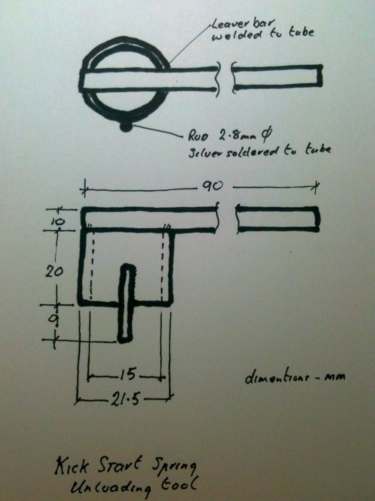
To make the reassembly of the return spring to the shaft a little simpler I made a tool.


This allowed the tension to be applied whilst inserting the retaining pin without loosing a finger.


                  The End

                          ( I hope )

Tuesday, 8 May 2012

THE THROTTLE CABLE


Whilst checking through the control cables I discovered that I was short of a throttle cable.  You might have thought that it would have been very obvious but as I said non of the cables were identified and none were terminated.  I guess I was bewitched by their nice shiny grey covers.

I got on to my new found friends at Cassa Lambretta, Danny (the LD expert) and Lee.  In no time at all I had a new throttle cable for only £2.50 plus P&P - bargain.  I also took the opportunity to buy two trunnions for the ends of the gear change cables (£2.08). I wonder where those bit went and why they were lost.

This nipple should be rotated by 90 degrees
I ran the cable through the frame on the correct rout.  My first problem was that when came to fit throttle end I had difficulty in getting the nipple to sit nicely in the twist grip.  No matter what I did the nipple always wanted to be at right angles to the recess in the twist griip.  I tried twisting the nipple to the position I wanted but it only sprung back the its original position.  If I tried to twist the nipple further, say through 120 degrees, the nipple would jump 180 degrees and so I was back in the same position.  I think there must be something wrong with the inner itself, a kink?

12 mm short
Having finally got the cable into the twist grip with the nipple sitting correctly in its recess and the assembly clamped tight on the handlebar I turned my attention to the other end.  Oh dear, it looks a bit short. (perhaps I said something a  little stronger than that)

I re checked everything  but the inner cable was still short.  Having slept on it I had two options, buy a new able or shorten the outer sheath.  I think the first was the best option because it might clear the nipple problem but I felt I could wait until I sent my next order to Danny.  In the mean time I would just have to shorten the outer by 12mm.  Easier said than done.

Firstly the end ferrel had to be removed.  This is swagged onto the end of the cable and can't just be pulled off.  By carefully cutting round the ferrel (using a junior hacksaw) above the swagging it was possible to remove it and cut through the swagged bit to remove that.  

Now for the outer.  Because both ends have crimped ends it is not possible to remove the inner cable.  This means that when cutting through the outer you have to be careful not to cut the inner cable.  By using the hacksaw again and carefully working my way round the outer progressively cutting into the wrapped steel outer it was possible to separate the end 12mm.  Now it only remained to cut off this short length, again without damaging the inner cable.  By holding the short length in a vice it was possible to cut along its length and finally produce a series of rings that then could be removed.  The inner low friction sheath was easy to remove with a knife.  With the outer/inner cable shortened I was able to glue the end ferrel back over the end of the outer sheath.  Job done, almost.

The cable fitted as I think it should and the carb throttle leaver operates with the with the twist grip.  BUT .....
I'm still not happy with the twist grip end nipple.  It was difficult to assemble and I think that because it is constantly trying to twist 90 degrees it will eventually do and then there is a change of failure.  Knowing my luck that will be at some most inconvenient moment.  I had a try at unsoldering the nipple before I realised that it was crimped onto the end of the cable.  In my day they were always soldered and I could have rectified the problem.  I will have a talk with Danny before ordering another cable.  I think it essential that the twist grip end nipple sits correctly and the length is right.

And now for the gear change cables.


CONTROL CABLES


When I bought the scooter the advert said that it had been fitted with "quality frictionless cables".  As the blog so far has indicated I've not been too interested in controlling anything.  Whilst waiting for a resolution on the kick start problem I thought it might be an idea to check out just what I had got with regard to control cables.


The cables had been tied onto the frame and run between the handle bars and the engine area.  Their function was not identified.  My first difficulty was to sort out what happened at the handlebars.  Referring to the limited number of pictures of the LD I found that the routing seemed to vary.  Sometimes the cables were run in front of the handle bars and sometimes behind.  I settled for the clutch and brake to run in front, the gear change and throttle behind.

 These pictures show one version of the routing.  From the other pictures I have seen I think it's more common for the break and clutch cables to cross over and thus avoid the sharp bend where they exit the leg shield.  

I don't have all the plastic sleeves so I have only fitted the pieces where the cables exit the leg shield.  I will eventually have to sort this out but my priority is still to get the scooter running.


 Thinking that he brakes would be a good place to start I worked on the rear first.  This avoided any involvement with the handlebars and so no dilemma.  Having purchased the necessary missing clamps etc I was able to connect both ends of the cable.  Once done I now had a rear brake - progress.

I had a small problem with fitting the nipple into the break leaver.  The slot for the cable was too tight to allow the cable to pass.  I think it was damage and not that the cable was thicker than normal.  A little filing soon sorted the problem.  I have to say that who ever made the pins for the brake leaver got the screw driver slots far too narrow.  I will have to make a special screw driver to fit so at the moment they are tight enough for testing but will need seeing to before a road test.  Will I remember?  

 Now for the throttle cable.  

Tuesday, 1 May 2012

THE KICK START START?


You may remember that I was having problems with replacing my kick start shaft.  Eventually on the 28/02/12 I sent the complete unit to Scooter Surgery for Patrick to investigate why I was having a problem.  On Saturday 28th April I received it back.  I think that it is chiefly due to Maude being on my case that it has finally came to the top of Patrick's pile.

I rushed down to the garage and found the kick start leaver, had the problem been solved?  I guess the immediate answer is NO. 


The leaver fits on the shaft as I would have expected but when I come to fit the clamp bolt the groove in the shaft does not line up with the the bolt in the leaver.  Disappointment hardly describes my feelings at the moment because this is where I had started.


Maude replied to my email saying that Patrick had fitted his LD leaver to the unit and all had been well.  The suggestion now is for me to take the scooter down to Hammersmith for Patrick to sort it out.  I'm not sure my pension would support that.  I have said that I need some time to investigate before making a decision on my next move.

Some good news, Patrick has not charged me for the time he has spent investigating, possibly encouraged by Maude.  I'm grateful and I don't want to fall out with them.  I look forward to taking the mechanism apart again and seeing what mods, if any, were made to the shaft.  

Saturday, 14 April 2012

ARE YOU SITTING COMFORTABLY

When I first bought the scooter I was impressed with the two new seat covers.  I thought "that's good at least I will have somewhere to sit".  As time went on I started to remember that there was a grab handle for the pillion.  I remembered that whilst sorting through the box of O & S i saw one.  I found it again and despite needing a new plastic cover it was as I remembered it.  

As a moment of diversion I thought it would be fun to fit it to ensure I had all the right bits.  When I came to look for the mounting holes on the rear saddle I couldn't see any.


I found them covered by the nose of the pillion seat cover.  No way could the handle be fitted.  


I kept coming back to the problem.  How could this be?  It became obvious that the seat cover was too long at the front.  In fact the front of the cover was unsupported and hung down.  The mounting holes were there, just covered.  Not another cock up!  Eventually I removed the seat cover by straightening out the securing clips taking care not to damage the cover material.


 Now I could see the handle fixing holes and the grab handle fixed easily in place.  So why was a wrong cover fitted?  I wondered if the covers could have been swapped and fitted on the wrong frames.  The one on the front looked smaller and the front nose length was defiantly shorter which is what I was looking for.


To check if the the front seat cover would fit on the pillion seat meant that I had to remove the pillion cover.  I hadn't noticed just how bad the fit of the cover on the front seat really was, something was wrong. With the cover removed I tried it on the pillion seat frame.  With a bit of adjustment it fitted and was defiantly the correct cover.   I'm convinced it was made for a pillion seat.  Unfortunately that leaves me with the question what does my rear cover fit, how do I get rid of it and where do I find a replacement front cover to match my pillion cover?

With the seat covers remover I had the opportunity to have a look at the seat springs.


The front seat wasn't too bad with all the springs in place. Some had see better days and were quite slack.


The pillion seat was in far worse condition with missing springs, some showing signs of having been over stretched.  
 I have no idea if it's possible to buy new springs and that will have to be investigated.  In the mean time I can always use them as they are, I'm not planning to ride to Italy or anywhere daft like that!   (2 Vespas 2 Italy)

Thursday, 12 April 2012

HANDLE BAR CONTROLS

The arrival of the brake/clutch leaver bolts inspired me to have a look at trying to sort out the conrtrols for the handle bars.  

K & S had been unable to supply me with the fixing bolts which clamp the two controls to the bars.  I had one of the originals (far right) and therefore could see what was needed.  I have given up the idea of being a purist during my restoration, I'm thinking more "inovator".  Relaxed by this revelation I was able to make a couple of bolts from some standard ones I had available.  The "cross head" is not correct but I'm sure Lambretta would have used them if they had been available.

The break/clutch leaver bolts are more sophisticated.  They provide the bearing surface for the leavers and their length is such as to prevent mounting casting being overtightened such that the leaver is pinched between the sides.  I notice that the slots in the bolt and the nut are very narrow.  To prevent damaging the slot I will need to use a wide bladed screwdriver.  My wide bladed drivers have much wider blades that will not fit.  I think I will have to either grind an existing blade or make a special one.  They need to be tight as i don't want them falling out whilst riding.


This is the right hand unit showing the showing the two bolts in position.  I think the cross head bolt looks OK and it appears to fit nicely into the counter sunk hole in the casting


Now I can concentrate on sorting the cables and fitting them to the handle bar controls.  I fancy the brakes first as they should be simplest.


Whilst starting to sort out the cable runs I notice that the two cables that drive the gear change mechanism don't have any ends on them.  The handle bar end has nipples but the other end is just a cable.  I certainly don't have ends and will now have to find if they are available or if I will have to make them.  Since I don't know what they look like this could be a problem.  The parts list identifies what I think I need as items 12,13 and 14.  They seem to work by clamping a disc onto the cable and holding it there with a grub screw.  At least I now have the confidence to see if I can buy the parts or at the worst make something.